

Overview of Servo motor : Flight Control
(Flight control) An experienced pilot is able to take-off an airplane smoothly, causing minimal discomfort to the passengers and crews onboard. The velocity profile of the airplane along the runway determines how smooth the takeoff will be. Figure 1. shows a possible velocity profile for a smooth take-off with three typical scenarios. The pilot tracks this profile via a servo control system, either on the actual airplane or for trainee pilots via a flight simulator.

The performance of a servo control system is therefore evaluated by indicators measuring how closely the objective reference signal is tracked, which is commonly based on the magnitude of the root-mean-square (RMS) tracking error over the profile. For point-to-point tracking (i.e. step change in reference signal), classical performance indicators can be used, including the rise time, overshoot, and steady state error. Figure 2 shows these indicators in relation to the response of the system to a unit step change in the reference signal.
This is a typical response of a secondorder system to a step change, which causes the output to increase above the set point, oscillate for some time, and eventually settle down at a steady-state value according to the set point value.
Figure 1 Velocity profile for plane take-off, with rotation speed VR and lift-off speed VLOF; (a) normal
rotation, (b) slow rotation, (c) under rotation
The amount of overshoot is usually indicated as a ratio of,
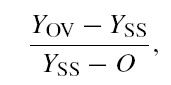
with respect to Figure 2.
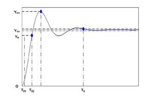
Figure 2 Classical performance indicator using step response of a system; O origin point, YSS steady-state value, YOV overshoot value, YR rising value, TR rise time, TS settling time
Settling time is determined by the time required by the output to stay within a certain amount of oscillation from the steady-state value, i.e. typically within ±1% of the steady-state value. There are several ways to determine rise time, one of which is the time from 10% to 90% of the output, i.e. TR2 −TR1.
Source : Andi Sudjana, Drives and Control for Industrial Automation, Springer Singapore 2011